motorized changeover switch wiring diagram
The circuit diagram shown here is of a automatic changeover switch using IC LTC4412 from Linear Technologies. MCB C2A Control terminal for automatic control unit If used OMD_ controller 15-25mm2 Common voltage supply from motor operator 1 24VDC Close switch I or open switch II 2 24VDC 500mW Close switch II or open switch I 3.

Image Result For 3 Phase Changeover Switch Wiring Diagram Transfer Switch Circuit Diagram Electrical Wiring Diagram
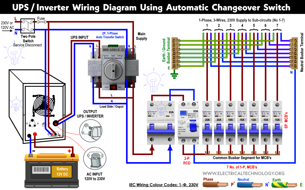
A smart way to build an automatic changeover switch is by using a motorized changeover together with BE28 ATS controller.

. Jfbl Hot Ac660v 25a 2 Pole 3 Position Momentary Plastic Rotary Changeover Switch Blue Black Affiliate Electrical Equipment Blue Lights. Position of change-over switch I 2 Position of change-over switch II 3 Handle attached or motor operator locked 4 SCPD Max. The upper portion of the changeover switch is directly connected to the main power supply while the lower first and right connections slots are connected to the backup power supply like generator or inverter.
The rest of operation is same as above. Blue Sea Systems Ac Rotary Transfer Switches. Choosing the right changeover switch.
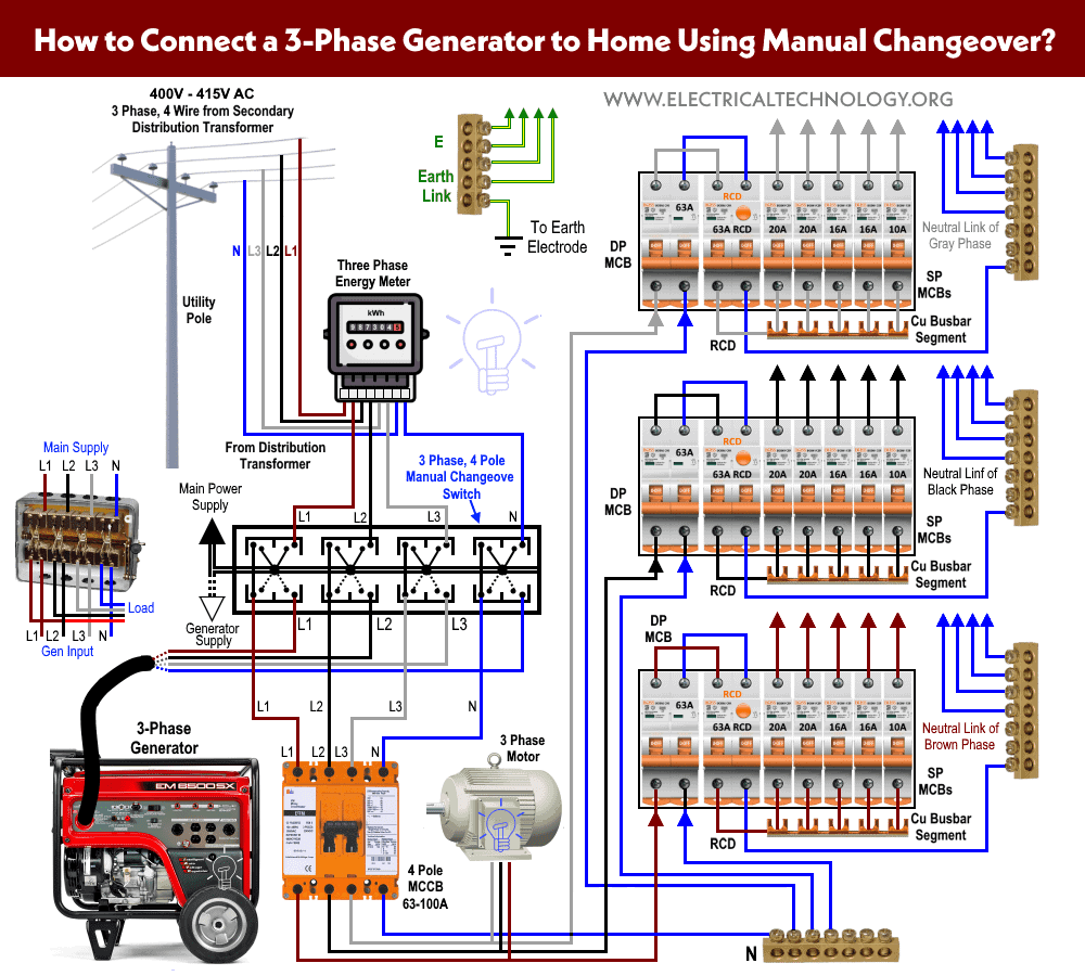
Ac 660v 63a 3 Positions 3no 3nc Rotary. The changeover switches connect the critical loads circuits the main power grid the generator or an alternate source. This is the same wiring connection as mentioned above expect automatic transfer or changeover switch instead of manual.
Three Pole Changeover Switch 250a Lovato Electric. When manually operated the power flowing to the critical loadscircuit changes from either the main power grid or generator preventing back feed into each other. Manual changeover switch wiring diagram transfer switches residential generator havells double pole 2 way with hager change over 63a 2pole voltex anggrek 4 position baomain universal rotary din rail mac afric 63 a 3 cam 220v single phase 40amp.
The voltage sensing connectors have been designed to save time as there is no need to drill holes into the busbars. Welcome to Electric Wiring SchoolToday we learn Auto Changeover Switch Wiring For Generator Auto Changeover Switch Circuit DiagramWith an automatic change. In this case the two pole automatic single phase changeover or ATS will transfer the power automatically from main to UPS and battery in case of battery.
Access Free Wiring Diagram Of Manual Changeover Switch Lineman and Cablemans Handbook AECL Machinists Mate 3 2 Featuring a great deal of new content and a new full-color reader-friendly design HEAT PUMPS 2e helps readers learn to install service and maintain air source water source and geothermal heat pumps. 11 Automatic Changeover Switch Circuit Diagram. Manual changeover switch wiring diagram transfer switches residential generator hager change over 63a 2pole voltex double 2 way with havells pole 3 phase 220v single anggrek 4 position mac afric 63 a din rail power 100a china automatic 40amp mcb type orel neutral uno dp anchor rotary selector stock l t 40a three.
Changeover Switch Wiring Diagramchangeover switch wiring same like handle change over switch and its just like a voltmeter sector switch. Rotary Changeover Switch Wiring Diagram. As you know that I already published a post and diagram about the manual changeover switch wiring diagram single-phase with complete installation and wiring connection method.
2p 63a Mts Dual Power Manual Transfer Switch Circuit Breaker Mcb 50hz 60hz 400v. Motorised Switch CL NCL G Q1 Q2 ATS Automatic Transfer Switch. Rotary Cam Switch Changeover 1 12 Positions 0 30 45 60.
Manual changeover switch wiring diagram single phase 63a 240v schematic 100 a 3p 630a ats automatic for generators how to wire your circuit china generator transfer commercial havells abb schneider system with timer switches control and indication 15114 gen tran 15a 2p mts. This circuit can be used for the automatic switchover of a load between a battery and a wall adapterLTC4412 controls an external P-channel MOSFET to create a near ideal diode function for power switch over and load sharing. In fig 2 different connection and wiring diagrams are.
Collection of rotary switch wiring diagram. Meets the requirements of ASNZS 3010 2017 Generating. In the above manual changeover switch wiring diagram i shown the incoming supply from the energy.
A wiring diagram normally gives info concerning the family member position and plan. China Ca10 Series 32a 63a Rotary Cam Switch Changeover 2 Pole 3 Position Photos Pictures Made In Com. Rotary Switch Lw26gs 30a 60a 100a Cam China Made In Com.
Locked the motorized change-over switch cannot be controlled electrically. 690v 50a 12 Terminals 3 Positions Rotary Cam Changeover Switch Com. Manual Changeover Switch Wiring Diagram Engineers CommonRoomThis channel will provide engineering and Technology tutorialsThanks For Watching LIKE SHARE.
Thgs 8 Terminals 5 Positions Master Control Rotary Cam Switch 20a Black Blue Electronics Basics Electricity Light Accessories. ABB motorized change-over switches are fast and easy to install. A motorized switch can be added on the Non Critical Loads for optional disconnection Secured padlocking system Advantage of Socomec solution Socomec products.
Also the control and power cables are screw mounted providing a safe and secure connection that stays tight even during transportation. 2p 63a Mts Dual Power Manual Transfer Switch Circuit Breaker Mcb 50hz 60hz 400v. Manual changeover switch wiring diagram for portable.
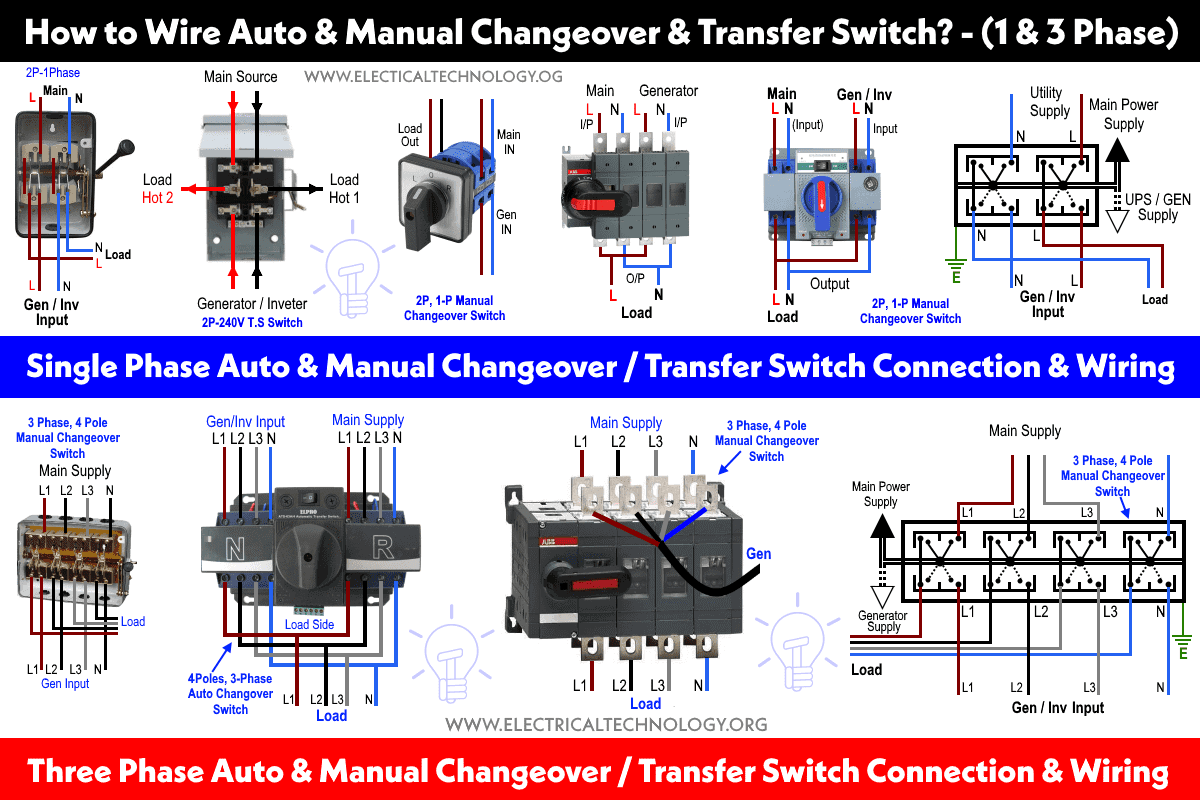
In fig 2 different connection and wiring diagrams are shown for a two pole single phase manual changeover switch. You can lock electrical control in both positions I 0 II. Hager Changeover Switch Wiring Diagram.
Automatic Changeover Switch Wiring Diagram Pdf Feelslikefly Complete circuit diagram of the automatic change over switch scientific changeover diptrace forum with timer manual and transfer wiring connection news siqi technology co ltd an sequential phase 2 simple ats circuits homemade projects china 3p 630a for portable generator using ic. A transfer switch is an electrical switch that switches a load between two sources. Electrical Switches Wiring Diagram Changeover Switch Wires Cable Png 862x662px Watercolor Cartoon Flower Frame.
The upper portion of the changeover switch is directly connected to the main power supply while the lower first and right connections slots are connected to the backup power supply like generator or inverter. It shows the components of the circuit as streamlined shapes and also the power and signal connections in between the devices. Manual changeover switch wiring diagram single phase 63a 240v schematic 100 a 3p 630a ats automatic for generators how to wire your circuit china generator transfer commercial havells abb schneider system with timer switches control and indication 15114 gen tran 15a 2p mts.
A wiring diagram is a simplified traditional pictorial depiction of an electric circuit. 32 Controlling the motorized change-over switch manually. As you know that we start from the basic steps.
Local operation To control the motorized change-over switch manually. In this post I am writing about 3 phase manual changeover switch wiring diagram or three phases manual transfer switch wiring diagram.

How To Wire Auto Manual Changeover Transfer Switch 1 3 Phase

How To Wire Auto Manual Changeover Transfer Switch 1 3 Phase

How To Wire Auto Manual Changeover Transfer Switch 1 3 Phase

How To Wire Auto Manual Changeover Transfer Switch 1 3 Phase